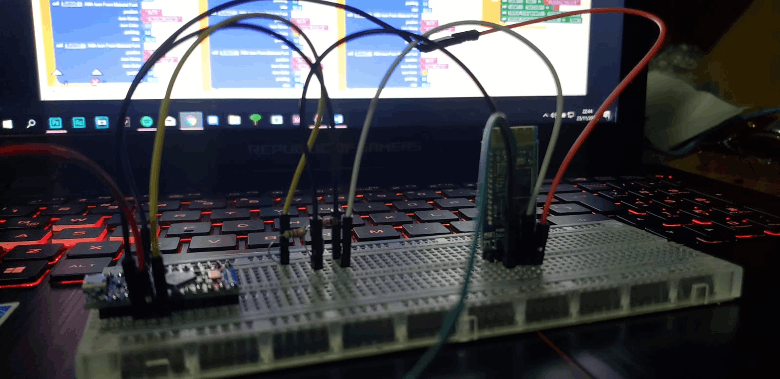
Prototipo en Arduino del módulo Bluetooth
Core v2
Showcase Interno de Core v2
Abrazo de Salud - Uso final
El código para frecuencia respiratoria simulación es un intento para poder replicar el sensor de frecuencia respiratoria.
int IFD = A0; // IR Fotodiodo
int IR = 2; // Infrarojo
int ambienteIR; // luz ambiente
int obstaculoIR; // si hay algún obstaculo
int valor[10]; // variable para guardar los valores
int distancia;
int ciclo;
int readIR;
void setup(){
Serial.begin(9600);
pinMode(IR,OUTPUT);
digitalWrite(IR,LOW);
}
void loop(){
int readIR(int ciclo);
{
for(int x=0;x
delay(1);
ambienteIR = analogRead(IFD);
digitalWrite(IR,HIGH);
delay(1);
obstaculoIR = analogRead(IFD);
valor[x] = ambienteIR-obstaculoIR;
}
for(int x=0;x
}
return(distancia/ciclo);
distancia = readIR(5);
Serial.println(distancia);
}
}
El código 2 del Bluetooth es el segundo intento en términos de código de Arduino para poder enviar los datos.
#include
SoftwareSerial BTserial(2, 3); // RX | TX
char c = ' ';
void setup()
{
Serial.begin(9600);
Serial.println("Inserta comandos");
BTserial.begin(9600);
}
void loop()
{
BTserial.println("97%");
Serial.println("97%");
delay(1000);
}
El código para bioimpedancia y voltaje funcionan en C.
#include "trtSettings.h"
#include "trtkernel_1284.c"
#include
#include
#include
#include
#include
#include
#include
#include
#include "lcd_lib.h"
// biblioteca de comunicaciones en serie
// No te metas con los semáforos
#define SEM_RX_ISR_SIGNAL 1
#define SEM_STRING_DONE 2 // el usuario presionó
#include "trtUart.c"
// descriptor de archivo UART
// putchar y getchar están en uart.c
ARCHIVO uart_str = FDEV_SETUP_STREAM (uart_putchar, uart_getchar, _FDEV_SETUP_RW);
// semáforo para proteger la variable compartida
#define SEM_SHARED 3
const int8_t LCD_initialize [] PROGMEM = "LCD inicializado \ 0";
// --- controlamos los LED desde los botones y uart --------------------
// ingresa argumentos a cada hilo
// no se usa realmente en este ejemplo
int args [2];
tampón de carbón [8];
// ********************************************** **********
// temporizador 0 desbordamiento ISR
ISR (TIMER0_COMPA_vect)
{
PORTB ^ = (1 << PINB3); // genera una onda cuadrada al alternar B3
}
// parámetros compartidos
uint16_t age;
uint16_t sex; // 1 si es hombre, 0 si es mujer
uint16_t peso;
float body_fat;
resistencia a la flotación;
char Ain;
// --- definimos la tarea 1 ----------------------------------------
estimación nula (void * args)
{
uint32_t rel, muerto;
mientras (1)
{
trtWait (SEM_SHARED);
// obtener la muestra
Ain = ADCH;
// iniciar otra conversión
ADCSRA | = (1 << ADSC);
// resistencia = (flotación) Ain * 5.0 / 255.0 / .000012; // convierte la lectura de ADC a voltaje bruto, R = V / I con un valor de corriente de 12 uA, del diseño del circuito
// calcula la grasa corporal con ecuaciones de regresión
si (sexo == 1)
{
body_fat = 0.0923 * peso + 0.1605 * edad - 0.0263 * (flotación) Ain;
}
más si (sexo == 0)
{
body_fat = 0.1871 * peso + 0.5800 * edad - 0.0920 * (flotación) Ain;
}
si (body_fat <0)
{
body_fat = 0.0;
}
trtSignal (SEM_SHARED);
// Dormir
rel = trtCurrentTime () + SECONDS2TICKS (0.04);
muerto = trtCurrentTime () + SECONDS2TICKS (0.04);
trtSleepUntil (rel, muerto);
}
}
// --- definimos la tarea 2 ----------------------------------------
void LCDComm (void * args)
{
uint32_t rel, muerto;
tampón de carbón [8];
mientras (1)
{
trtWait (SEM_SHARED);
// imprime el porcentaje de grasa y los parámetros
LCDGotoXY (0,0);
si (body_fat! = 0)
{
sprintf (búfer, "Grasa corporal:% .1f %%", grasa corporal);
LCDstring (búfer, strlen (búfer));
LCDGotoXY (0,1);
sprintf (búfer, "A:% i W:% i G:% i", edad, peso, sexo);
LCDstring (búfer, strlen (búfer));
}
más
{
sprintf (búfer, "No listo");
LCDstring (búfer, strlen (búfer));
LCDGotoXY (0,1);
sprintf (búfer, "Sin entrada");
LCDstring (búfer, strlen (búfer));
}
trtSignal (SEM_SHARED);
// Dormir
rel = trtCurrentTime () + SECONDS2TICKS (0.2);
muerto = trtCurrentTime () + SECONDS2TICKS (0.4);
trtSleepUntil (rel, muerto);
}
}
// --- definimos la tarea 3 ----------------------------------------
void serialComm (void * args)
{
char cmd [5];
float input_arg;
mientras (1)
{
// comandos:
fprintf (salida estándar, ">");
fscanf (stdin, "% s% f", cmd, & input_arg);
trtWait (SEM_STRING_DONE);
// actualizar los parámetros compartidos
trtWait (SEM_SHARED);
si (cmd [0] == 'a')
{
edad = input_arg;
}
si (cmd [0] == 'g')
{
sex = input_arg;
}
si (cmd [0] == 'w')
{
peso = entrada_arg;
}
trtSignal (SEM_SHARED);
}
}
/* Includes ------------------------------------------------------------------*/
#include "main.h"
/** @addtogroup STM32F429I_DISCOVERY_Examples
* @{
*/
/** @addtogroup ADC_DMA
* @{
*/
/* Private typedef -----------------------------------------------------------*/
/* Private define ------------------------------------------------------------*/
#define MESSAGE0 "ADC =%5d"
#define MESSAGE "ADC =%4d"
#define MESSAGE1 "ADC conversion w/DMA"
#define MESSAGE1_1 "continuouslyTransfer"
#define MESSAGE2 " ADC PG13 Conv "
#define MESSAGE2_1 " 2.4Msps "
#define MESSAGE5 " ADC3 = %d.%1d V "
#define MESSAGE6 " ADC2 = %d.%1d V "
#define LINENUM 0x15
#define FONTSIZE Font12x12
#define ADC2_DR_ADDRESS ((uint32_t)0x4001124C)
#define ADC3_DR_ADDRESS ((uint32_t)0x4001224C)
#define ADC_CCR_ADDRESS ((uint32_t)0x40012308)
#define DMA_STREAM DMA2_Stream0
#define DMA_IT_TCIF DMA_IT_TCIF0
#define DMA_STREAM_IRQ DMA2_Stream0_IRQn
/* Private macro -------------------------------------------------------------*/
/* Private variables ---------------------------------------------------------*/
uint16_t n;
uint32_t t;
uint16_t D1=0,D2=0;
char Text[20];
__IO uint16_t aADCDualConvertedValue[2],Aux=0;
__IO uint16_t Muest=0;
/* You can monitor the converted value by adding the variable "uhADC3ConvertedValue"
to the debugger watch window */
__IO uint16_t uhADC3ConvertedValue = 0,uhADC2ConvertedValue = 0;
__IO uint32_t uwADC3ConvertedVoltage = 0,uwADC2ConvertedVoltage = 0;
uint16_t Res=0,Res1=0,Res0=0;
/* Private function prototypes -----------------------------------------------*/
static void DMA_Config(void);
static void GPIO_Config(void);
static void ADC1_CH13_Config(void);
static void ADC2_CH5_Config(void);
void R_ADC(void);
#ifdef USE_LCD
static void Display_Init(void);
void Init_GPIO(void);
#endif /* USE_LCD */
/**
* @brief Main program
* @param None
* @retval None
*/
int main(void)
{
ADC_CommonInitTypeDef ADC_CommonInitStructure;
/* Enable peripheral clocks *************************************************/
RCC_AHB1PeriphClockCmd(RCC_AHB1Periph_DMA2, ENABLE);
RCC_AHB1PeriphClockCmd(RCC_AHB1Periph_GPIOA, ENABLE);
RCC_AHB1PeriphClockCmd(RCC_AHB1Periph_GPIOC, ENABLE);
RCC_APB2PeriphClockCmd(RCC_APB2Periph_ADC1, ENABLE);
RCC_APB2PeriphClockCmd(RCC_APB2Periph_ADC2, ENABLE);
Init_GPIO();
GPIO_Config();
#ifdef USE_LCD
/* LCD Display init */
Display_Init();
#endif /* USE_LCD */
/* DMA2 Stream0 channel0 configuration **************************************/
DMA_Config();
/* ADC Common Init */
ADC_CommonInitStructure.ADC_Mode = ADC_DualMode_RegSimult;
ADC_CommonInitStructure.ADC_Prescaler = ADC_Prescaler_Div2;
ADC_CommonInitStructure.ADC_DMAAccessMode = ADC_DMAAccessMode_1;
ADC_CommonInitStructure.ADC_TwoSamplingDelay = ADC_TwoSamplingDelay_5Cycles;
ADC_CommonInit(&ADC_CommonInitStructure);
/* ADC1 regular channels 10, 11 configuration */
ADC1_CH13_Config();
/* ADC2 regular channels 11, 12 configuration */
ADC2_CH5_Config();
/* Enable DMA request after last transfer (Multi-ADC mode) */
ADC_MultiModeDMARequestAfterLastTransferCmd(ENABLE);
ADC_DMACmd(ADC1,ENABLE);
ADC_DMACmd(ADC2,ENABLE);
/* Enable ADC1 */
ADC_Cmd(ADC1, ENABLE);
/* Enable ADC2 */
ADC_Cmd(ADC2, ENABLE);
ADC_ContinuousModeCmd(ADC1,ENABLE);
ADC_ContinuousModeCmd(ADC2,ENABLE);
/* Start ADCx Software Conversion */
ADC_SoftwareStartConv(ADC1);
ADC_SoftwareStartConv(ADC2);
LCD_SetFont(&Font16x24);
LCD_SetTextColor(LCD_COLOR_RED);
//LCD_DisplayStringLine(LCD_LINE_1,"AnaLogic");
GPIO_SetBits(GPIOE, GPIO_Pin_6);
GPIO_SetBits(GPIOE, GPIO_Pin_4);
while (1)
{
/* convert the ADC value (from 0 to 0xFFF) to a voltage value (from 0V to 3.0V)*/
//ADC1 Channel 13 -> PC3
//ADC2 Channel 5 -> PA5
/* Display ADCs converted values on LCD */
#ifdef USE_LCD
for(n=0;n<1920;n++)
{
LCD_SetTextColor(LCD_COLOR_BLUE);
//Aux=aADCDualConvertedValue[1]-100;
//if((Aux)<0){Aux=1;}
LCD_DrawFullCircle(n/8, 1+(Res), 1);
snprintf(Text, sizeof(Text), "%d", Res);
LCD_SetTextColor(LCD_COLOR_BLACK);
LCD_DisplayStringLine(LCD_LINE_1,(uint8_t*)Text);
//for(t=0;t<100000;t++){;}
R_ADC();
}
LCD_Clear(LCD_COLOR_GREY);
//Display(); (240x320)
//Resolución 320 x 480 Pixi LCD Cel
/*LCD_SetTextColor(LCD_COLOR_WHITE);
LCD_DrawFullRect(40, 0, 150, 320);
D2=10+aADCDualConvertedValue[1];
LCD_SetTextColor(LCD_COLOR_BLUE);
LCD_DrawFullRect(140, 0, 50, D2);*/
#endif /* USE_LCD */
}
}
void R_ADC()
{
//IRLed_On **********************
GPIO_ResetBits(GPIOE, GPIO_Pin_4);
for(t=0;t<50000;t++){;}
Res1=aADCDualConvertedValue[1];
if(Res1>1000){Res1=0;}
//IRLed_Off **********************
GPIO_SetBits(GPIOE, GPIO_Pin_4);
for(t=0;t<50000;t++){;}
Res0=aADCDualConvertedValue[1];
if(Res0>1000){Res0=0;}
// 1 0
Res=Res1-Res0;
if(Res>1000){Res=1;}
if(Res<1){Res=0;}
}
/**
* @brief ADC1 regular channels 10 and 11 configuration
* @param None
* @retval None
*/
static void ADC1_CH13_Config(void)
{
ADC_InitTypeDef ADC_InitStructure;
ADC_InitStructure.ADC_Resolution = ADC_Resolution_10b;
ADC_InitStructure.ADC_ScanConvMode = ENABLE;
ADC_InitStructure.ADC_ContinuousConvMode = ENABLE;
ADC_InitStructure.ADC_ExternalTrigConvEdge = ADC_ExternalTrigConvEdge_None;
ADC_InitStructure.ADC_ExternalTrigConv = ADC_ExternalTrigConv_T1_CC1;
ADC_InitStructure.ADC_DataAlign = ADC_DataAlign_Right;
ADC_InitStructure.ADC_NbrOfConversion = 1;//2
ADC_Init(ADC1, &ADC_InitStructure);
/* ADC1 regular channel 3 configuration */
ADC_RegularChannelConfig(ADC1, ADC_Channel_13, 1, ADC_SampleTime_3Cycles);
//ADC_RegularChannelConfig(ADC1, ADC_Channel_11, 2, ADC_SampleTime_3Cycles);
}
static void ADC2_CH5_Config(void)
{
ADC_InitTypeDef ADC_InitStructure;
ADC_InitStructure.ADC_Resolution = ADC_Resolution_10b;
ADC_InitStructure.ADC_ScanConvMode = ENABLE;
ADC_InitStructure.ADC_ContinuousConvMode = ENABLE;
ADC_InitStructure.ADC_ExternalTrigConvEdge = ADC_ExternalTrigConvEdge_None;
ADC_InitStructure.ADC_ExternalTrigConv = ADC_ExternalTrigConv_T1_CC1;
ADC_InitStructure.ADC_DataAlign = ADC_DataAlign_Right;
ADC_InitStructure.ADC_NbrOfConversion = 1;//2
ADC_Init(ADC2, &ADC_InitStructure);
/* ADC2 regular channel 5 configuration */
ADC_RegularChannelConfig(ADC2, ADC_Channel_5, 1, ADC_SampleTime_3Cycles);
//ADC_RegularChannelConfig(ADC2, ADC_Channel_12, 2, ADC_SampleTime_3Cycles);
}
/**
* @brief DMA Configuration
* @param None
* @retval None
*/
static void DMA_Config(void)
{
DMA_InitTypeDef DMA_InitStructure;
NVIC_InitTypeDef NVIC_InitStructure;
DMA_InitStructure.DMA_Channel = DMA_Channel_0;
DMA_InitStructure.DMA_Memory0BaseAddr = (uint32_t)&aADCDualConvertedValue;
DMA_InitStructure.DMA_PeripheralBaseAddr = (uint32_t)ADC_CCR_ADDRESS;
DMA_InitStructure.DMA_DIR = DMA_DIR_PeripheralToMemory;
DMA_InitStructure.DMA_BufferSize = 2;
DMA_InitStructure.DMA_PeripheralInc = DMA_PeripheralInc_Disable;
DMA_InitStructure.DMA_MemoryInc = DMA_MemoryInc_Enable;
DMA_InitStructure.DMA_PeripheralDataSize = DMA_PeripheralDataSize_HalfWord;
DMA_InitStructure.DMA_MemoryDataSize = DMA_MemoryDataSize_HalfWord;
DMA_InitStructure.DMA_Mode = DMA_Mode_Circular;
DMA_InitStructure.DMA_Priority = DMA_Priority_High;
DMA_InitStructure.DMA_FIFOMode = DMA_FIFOMode_Enable;
DMA_InitStructure.DMA_FIFOThreshold = DMA_FIFOThreshold_HalfFull;
DMA_InitStructure.DMA_MemoryBurst = DMA_MemoryBurst_Single;
DMA_InitStructure.DMA_PeripheralBurst = DMA_PeripheralBurst_Single;
DMA_Init(DMA2_Stream0, &DMA_InitStructure);
/* DMA2_Stream0 enable */
DMA_Cmd(DMA2_Stream0, ENABLE);
//Enable DMA Stream Transfer Complete interrupt
DMA_ITConfig(DMA_STREAM, DMA_IT_TC, ENABLE);
// Enable the DMA Stream IRQ Channel
NVIC_InitStructure.NVIC_IRQChannel = DMA_STREAM_IRQ;
NVIC_InitStructure.NVIC_IRQChannelPreemptionPriority = 5;
NVIC_InitStructure.NVIC_IRQChannelSubPriority = 0;
NVIC_InitStructure.NVIC_IRQChannelCmd = ENABLE;
NVIC_Init(&NVIC_InitStructure);
}
/**
* @brief Configure ADC Channels 10, 11, 12 pins as analog inputs
* @param None
* @retval None
*/
static void GPIO_Config(void)
{
GPIO_InitTypeDef GPIO_InitStructure;
/*
ADC1 Channel 13 -> PC3
ADC2 Channel 5 -> PA5
*/
GPIO_InitStructure.GPIO_Pin = GPIO_Pin_3;
GPIO_InitStructure.GPIO_Mode = GPIO_Mode_AN;
GPIO_InitStructure.GPIO_PuPd = GPIO_PuPd_NOPULL ;
GPIO_Init(GPIOC, &GPIO_InitStructure);
GPIO_InitStructure.GPIO_Pin = GPIO_Pin_5;
GPIO_InitStructure.GPIO_Mode = GPIO_Mode_AN;
GPIO_InitStructure.GPIO_PuPd = GPIO_PuPd_NOPULL ;
GPIO_Init(GPIOA, &GPIO_InitStructure);
}
volatile uint8_t i;
void DMA2_Stream0_IRQHandler(void)
{
GPIO_ToggleBits(GPIOG, GPIO_Pin_13);
//GPIO_SetBits(GPIOG, GPIO_Pin_14);
Muest++;
// Test on DMA Stream Transfer Complete interrupt
if (DMA_GetITStatus(DMA_STREAM, DMA_IT_TCIF))
{
// Clear DMA Stream Transfer Complete interrupt pending bit
DMA_ClearITPendingBit(DMA_STREAM, DMA_IT_TCIF);
i = 1;//hay diferencia kon esto y sin esto
}
}
void Init_GPIO(void)
{
GPIO_InitTypeDef GPIO_InitStruct; //PORTG
RCC_AHB1PeriphClockCmd(RCC_AHB1Periph_GPIOG, ENABLE);
RCC_AHB1PeriphClockCmd(RCC_AHB1Periph_GPIOE, ENABLE);
GPIO_InitStruct.GPIO_Pin = GPIO_Pin_13 | GPIO_Pin_14; // we want to configure all LED GPIO pins
GPIO_InitStruct.GPIO_Mode = GPIO_Mode_OUT; // we want the pins to be an output
GPIO_InitStruct.GPIO_Speed = GPIO_Speed_100MHz; // this sets the GPIO modules clock speed
GPIO_InitStruct.GPIO_OType = GPIO_OType_PP; // this sets the pin type to push / pull (as opposed to open drain)
GPIO_InitStruct.GPIO_PuPd = GPIO_PuPd_NOPULL; // this sets the pullup / pulldown resistors to be inactive
GPIO_Init(GPIOG, &GPIO_InitStruct); // this finally passes all the values to the GPIO_Init function which takes care of setting the corresponding bits.
GPIO_InitStruct.GPIO_Pin = GPIO_Pin_6 | GPIO_Pin_4; // we want to configure all LED GPIO pins
GPIO_InitStruct.GPIO_Mode = GPIO_Mode_OUT; // we want the pins to be an output
GPIO_InitStruct.GPIO_Speed = GPIO_Speed_100MHz; // this sets the GPIO modules clock speed
GPIO_InitStruct.GPIO_OType = GPIO_OType_PP; // this sets the pin type to push / pull (as opposed to open drain)
GPIO_InitStruct.GPIO_PuPd = GPIO_PuPd_NOPULL; // this sets the pullup / pulldown resistors to be inactive
GPIO_Init(GPIOE, &GPIO_InitStruct);
}
#ifdef USE_FULL_ASSERT
void assert_failed(uint8_t* file, uint32_t line)
{
while (1)
{
}
}
Prototipo en Arduino del módulo Bluetooth
El código para SpO2, Temperatura y Bluetooth 1 ha compilado, sin embargo no podemos probar el envio de datos, ya que no tenemos los sensores.
#include "MAX30100_PulseOximeter.h"
#include
#include
#define Addr 0x40 //temperatura
#define periodo_informacion_MS 1000 //max30100
PulseOximeter pox;
uint32_t reporte_final = 0;
SoftwareSerial miBT(2,3); // BLuetooth puertos
char dato_max30100 ;
void setup()
{
// Bluetooth
Serial.begin(9600);
Serial.println("listo");
miBT.begin(38400);
// declaraciones del sensor de temperatura
Wire.begin();
Serial.begin(9600);
Wire.beginTransmission(Addr);
Wire.endTransmission();
delay(300);
// declaraciones del max
Serial.begin(115200);
Serial.print("INICIANDO MEDIDAS");
if (!pox.begin()) {
Serial.println("FAILED");
for(;;);
} else {
Serial.println("SUCCESS");
}
pox.setIRLedCurrent(MAX30100_LED_CURR_7_6MA);
}
void loop()
{
unsigned int data[2]; // aca empieza lo de temperatura
Wire.beginTransmission(Addr);
Wire.write(0xF5);
Wire.endTransmission();
delay(500);
Wire.requestFrom(Addr, 2);
if(Wire.available() == 2)
{
data[0] = Wire.read();
data[1] = Wire.read();
}
float humedad = ((data[0] * 256.0) + data[1]);
humedad = ((125 * humedad) / 65536.0) - 6;
Wire.beginTransmission(Addr);
Wire.write(0xF3);
Wire.endTransmission();
delay(500);
Wire.requestFrom(Addr, 2);
if(Wire.available() == 2)
{
data[0] = Wire.read();
data[1] = Wire.read();
}
float temp = ((data[0] * 256.0) + data[1]); // CON ESTO SE CONVIERTE LA DATA
float cTemp = ((175.72 * temp) / 65536.0) - 46.85;
float fTemp = cTemp * 1.8 + 32;
// SALIDAS
Serial.print("Humeda Relativa : ");
Serial.print(humedad);
Serial.println(" % RH");
Serial.print("Temperatura en Celsius : ");
Serial.print(cTemp);
Serial.println(" C");
delay(500);
if (Serial.available())
miBT.write(Serial.read()); // lee Arduino y envia a BT
if (millis() - reporte_final > periodo_informacion_MS) {
Serial.print("bpm / SpO2:");
Serial.print(pox.getSpO2());
Serial.println("%");
reporte_final = millis();
if (Serial.available())
miBT.write(Serial.read()); // lee Arduino y envia a
}
}
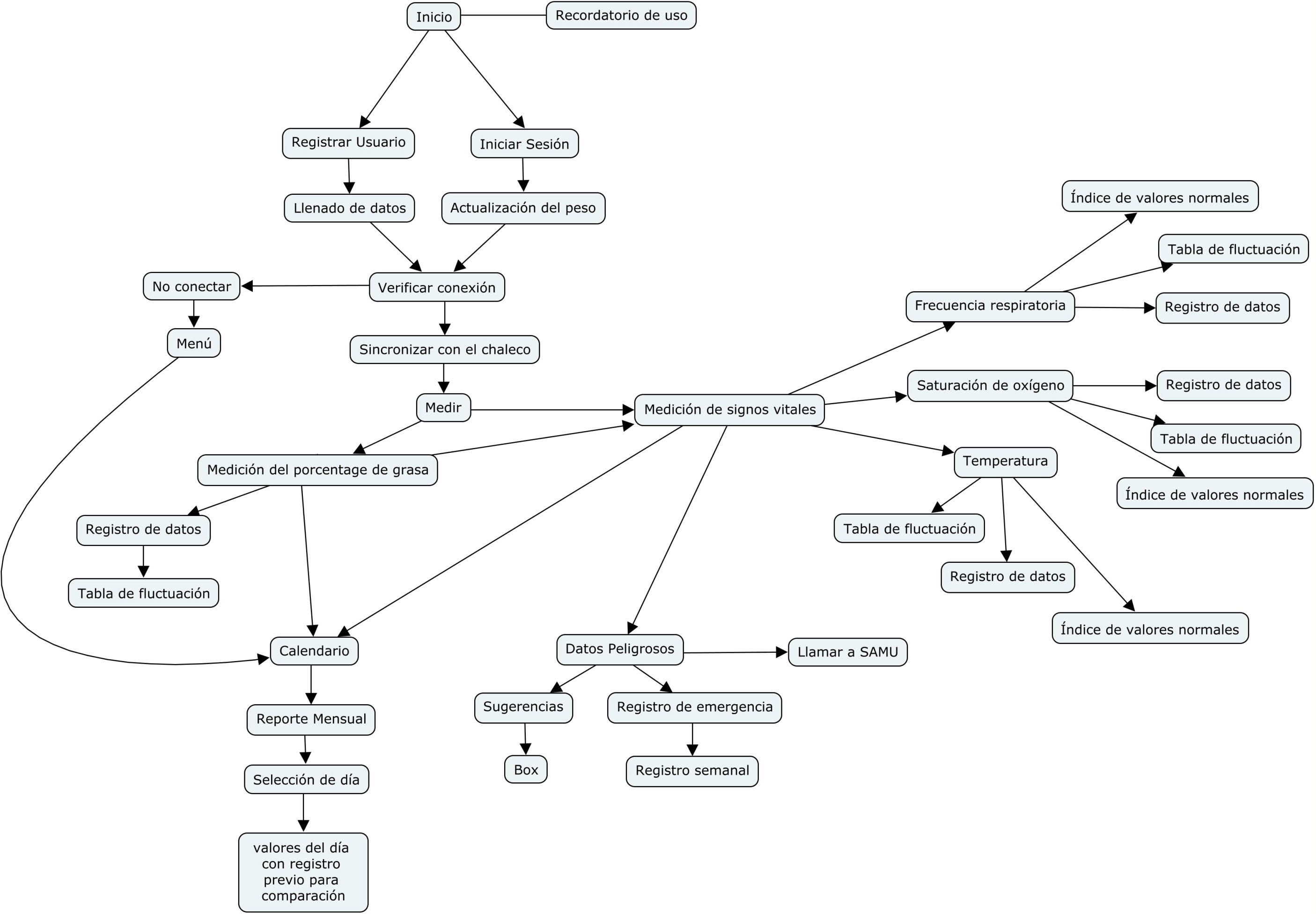
CMAPTOOLS
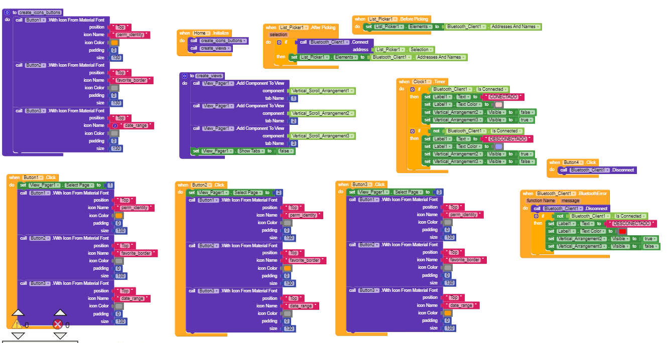
Código de la aplicación desde Kodular
This web page was designed with Mobirise